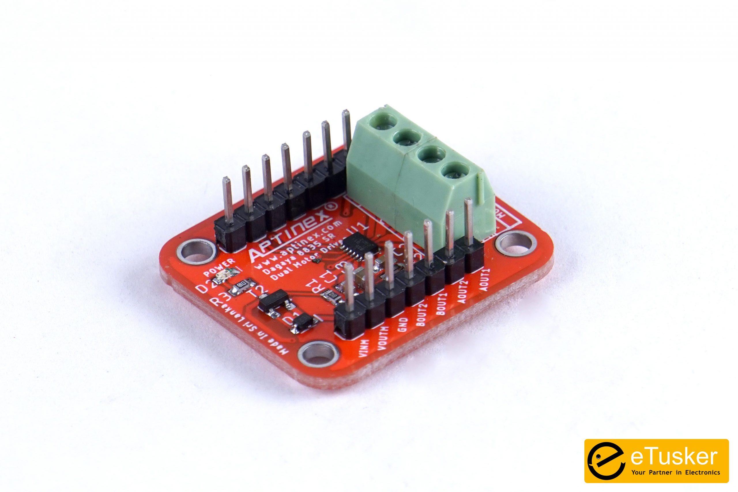
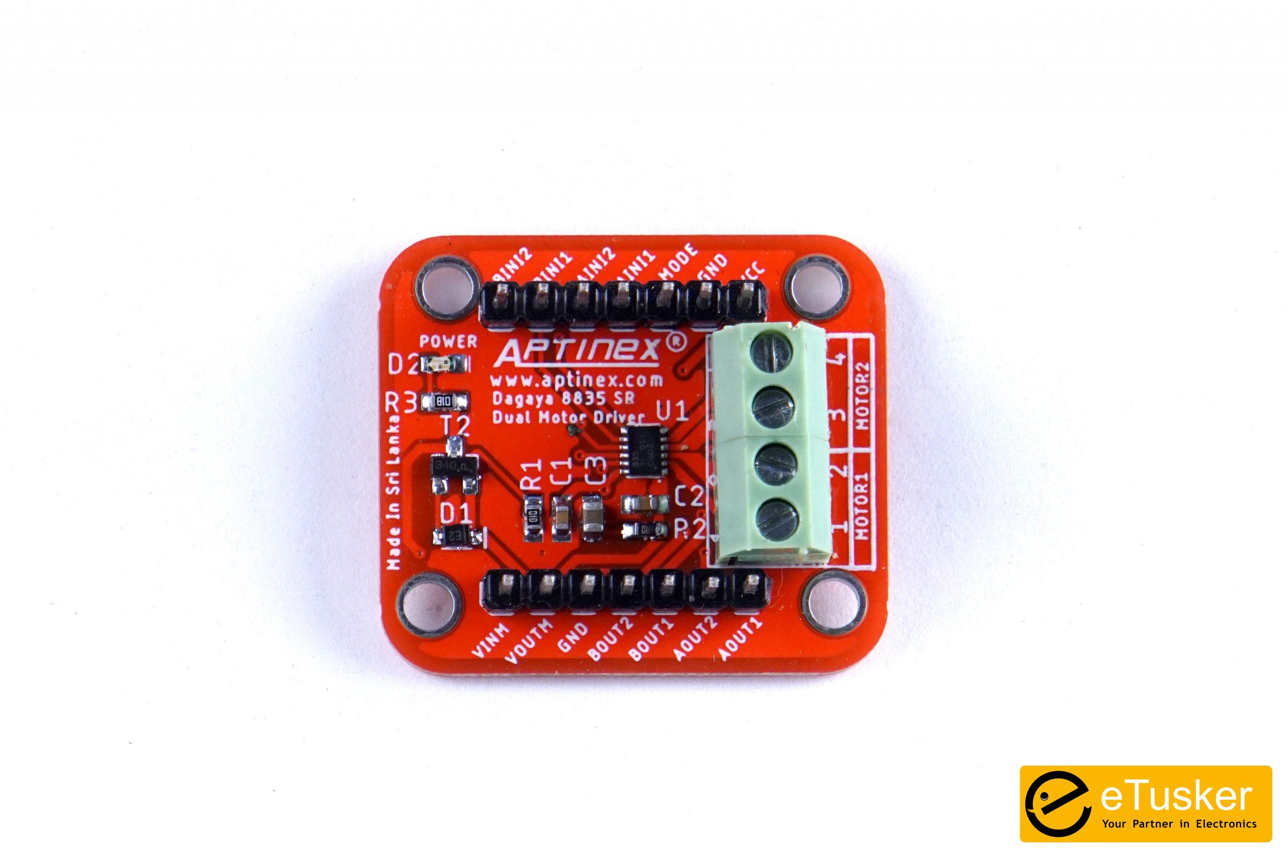
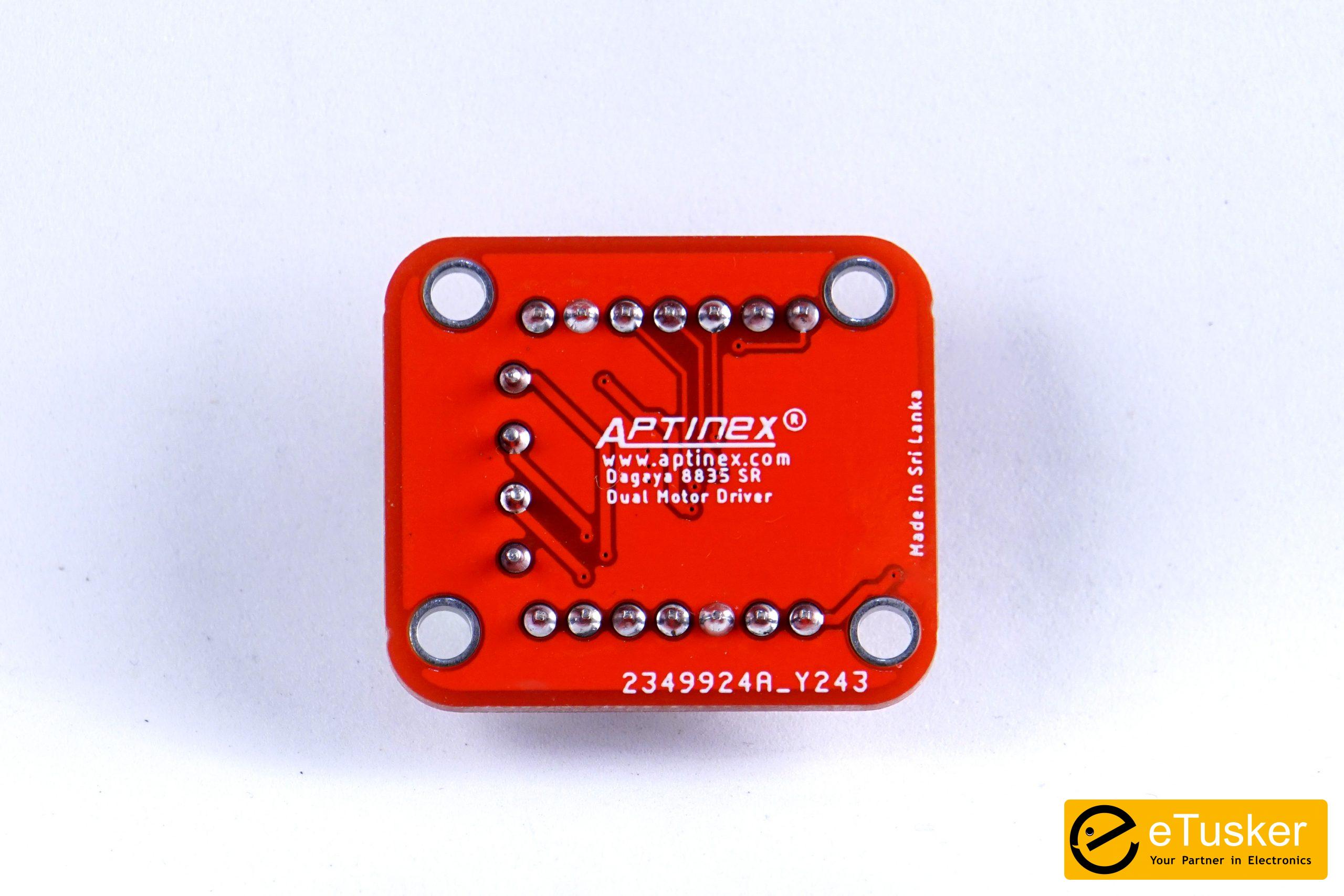
Aptinex Dagaya 8835DSSR – DRV8835DSSR Based Dual Motor Driver (2 Channel)
Roll over image to zoom in
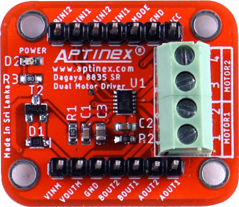
The Dangaya 8835DSSR is a compact breakout board for the TI’s DRV8835 dual motor driver. This component is capable of providing up to 1.5A current to a pair of DC motors. Its operating voltage ranges in between 0V to 11V and can provide a device power supply voltage between 2V to 7V making it an attractive component to use when powering two low voltage motors, solenoids, or a stepper motor. The device supports two control modes which of IN/IN and PHASE/ENABLE for added flexibility.
The DRV8835 provides an integrated motor driver solution for cameras, consumer products, toys, and other low-voltage or battery-powered motion control applications. The device has two H-bridge drivers, and drives two DC motors or one stepper motor, as well as other devices like solenoids. The output driver block for each consists of N-channel power MOSFETs configured as an H-bridge to drive the motor winding. An internal charge pump generates gate drive voltages. The DRV8835 supplies up to 1.5-A of output current per H-bridge and operates on a motor power supply voltage from 0 V to 11 V, and a device power supply voltage of 2 V to 7 V.
Features
- Dual-H-Bridge Motor Driver
- Capable of Driving Two DC Motors or One Stepper Motor
- Low MOSFET ON Resistance: HS + LS 305mΩ
- 1.5-A Maximum Drive Current Per H-Bridge
- Configure Bridges Parallel for 3-A Drive Current
- Separate Motor and Logic-Supply Pins:
- 0-V to 11-V Motor-Operating Supply-Voltage
- 2-V to 7-V Logic Supply-Voltage
- Flexible PWM or PHASE/ENABLE Interface
- Low-Power Sleep Mode With 95-nA Maximum Supply Current
- Tiny 2.00-mm × 3.00-mm WSON Package
Included Hardware
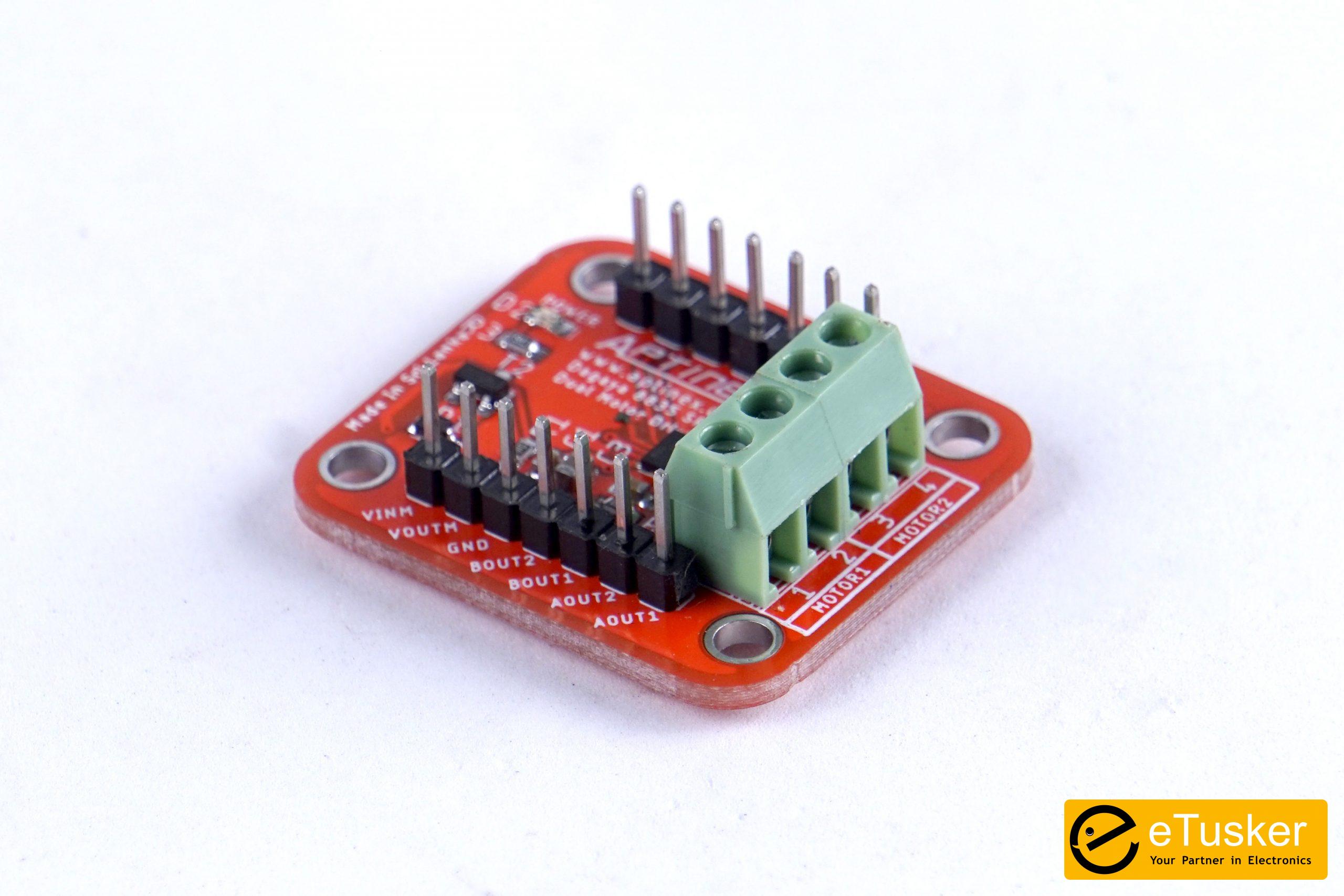
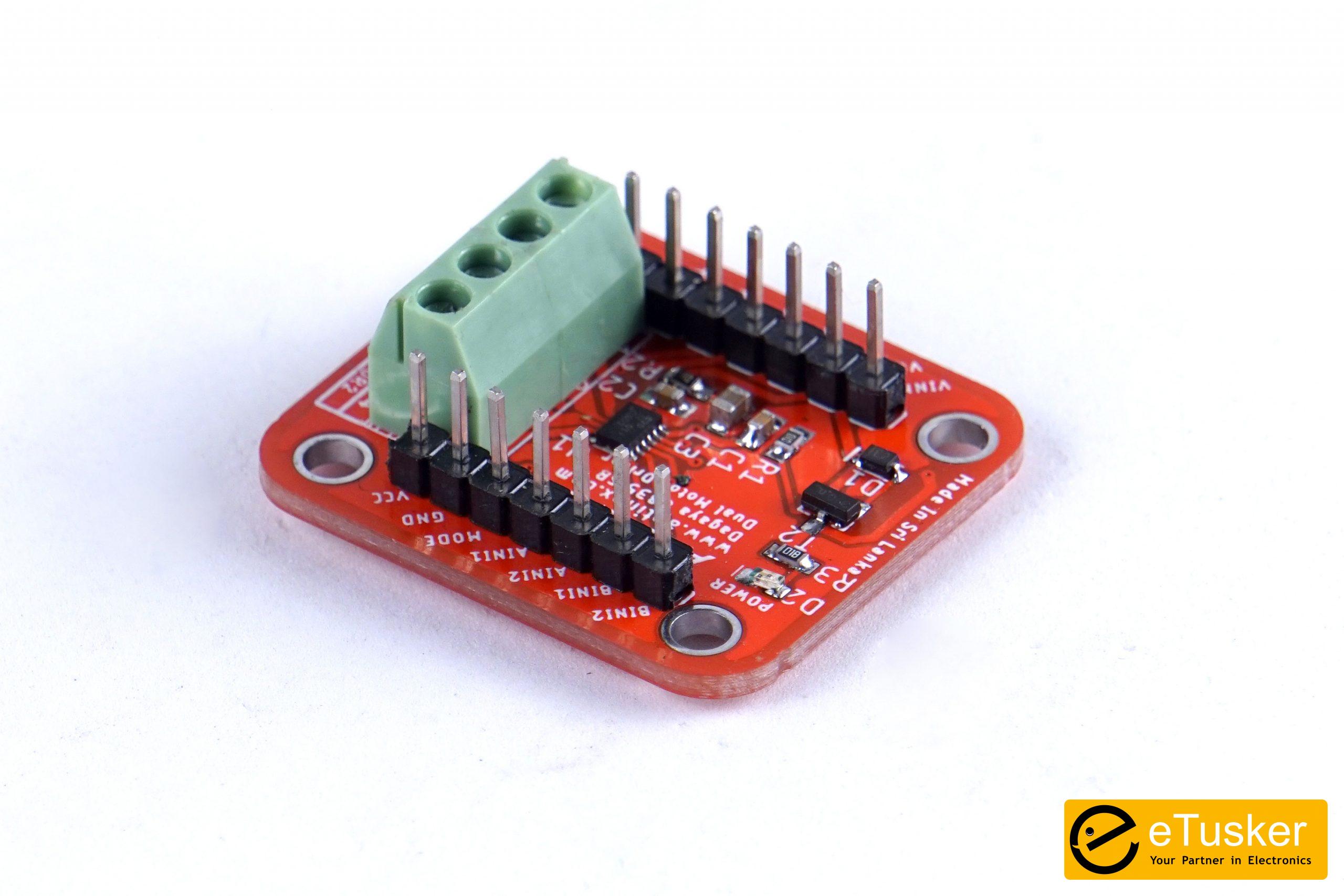
The component is shipped fully packaged and as represented in product images; with two 1×7-pin breakaway 0.1” inch male header soldered onto the board.
Using the Motor Driver
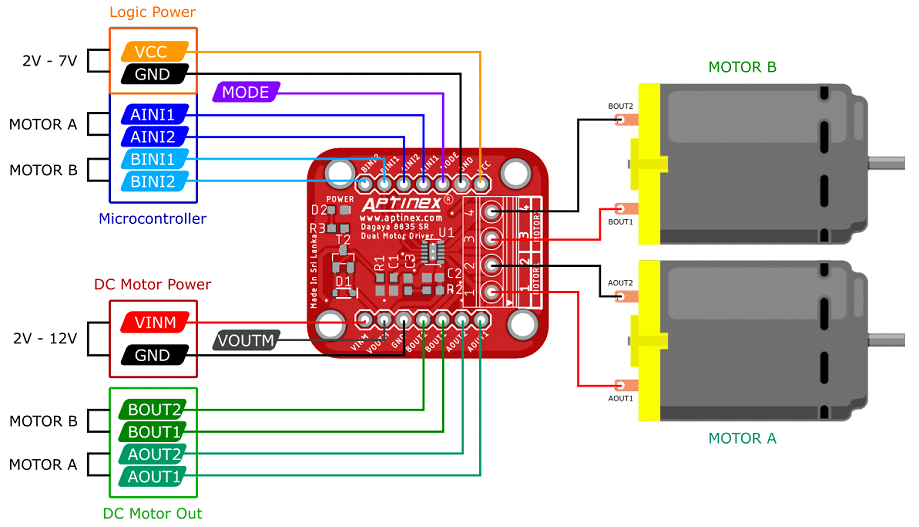
One side of the board is dedicated for the motor and motor power control connections and the other side is dedicated to the logic power and control connections. To function, this driver requires an input voltage of 0V – 11V to be supplied to the VIN and the VMM pins and a logic level between 2V and 7V to be supplied to the VIN pin which can be supplied through a controlling device. The VIN pin is recommended to be used as the motor supply input as it has a reverse-protection circuit integrated. However, the performance of the driver may worsen when the input to the VIN pin is below 2V. Therefore, when used for applications that require below 2V input, the supply can be directly connected to the VMM pin which bypasses the reverse protection circuit.
TI’s DRV8835 IC integrated in the motor driver supports two control modes; IN/IN and PHASE/ENABLE, which can be controlled using the MODE pin. If the MODE pin is left disconnected the driver will be in IN/IN mode where the driver outputs are disabled by default. The MODE pin can be set to HIGH by using a pull-up resistor or by a high I/O line which changes the mode to PHASE/ENABLE. In this mode the PHASE pin determines the motor direction and the ENABLE pin can be supplied with a PWM signal to control the motor speed. While the PHASE/ENABLE mode is easier to implement as it only requires one PWM signal, it only allows drive/break operation, whereas the IN/IN mode also provides drive/coast options in addition.
Connection Diagram
Pinout
| PIN | DEFAULT STATE | DESCRIPTION |
|---|---|---|
| VIN | – | Reverse protected motor supply input with a recommended input above 2V as the reverse protection circuit will start affecting the performance below 2V (Lower limit: 1.5V) |
| VCC | – | 2V – 7V logic power supply connection |
| VMM | – | Used to supply reverse-protected power to other components. Can be used to supply board power in low voltage scenarios |
| GND | – | Common ground for motor and logic power supplies |
| AOUT1 | – | Motor A half-bridge 1 output |
| AOUT2 | – | Motor A half-bridge 2 output |
| BOUT1 | – | Motor B half-bridge 1 output |
| BOUT2 | – | Motor B half-bridge 2 output |
| AIN1 | LOW | Logic input control for motor channel A |
| AIN2 | LOW | Logic input control for motor channel A |
| BIN1 | LOW | Logic input control for motor channel B |
| BIN2 | LOW | Logic input control for motor channel B |
| MODE | LOW | Logic low on this pin enables IN/IN mode. Logic high enables PHASE/ENABLE mode |
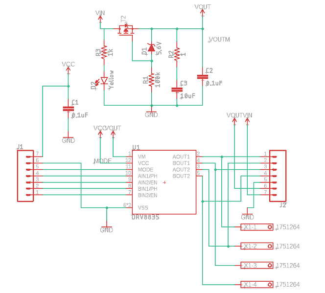
Schematic
Additional information
| Weight | 10 g |
|---|