-
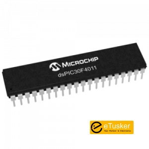
dsPIC30F4011 – PDIP
dspic 30f4011 microcontroller includes a large 48kB internal flash memory and a wide range of timers together with a number of PWM modules for adjustable motor speed control.
Features of dspic30f4011
- High – Performance Modified RISC CPU
- Modified Harvard architecture
- C compiler optimized instruction set architecture
- 84 base instructions with flexible addressing modes
- 24-bit wide instructions, 16-bit wide data path
- 16 x 16-bit working register array
- Up to 30 MIPs operation :
- DC to 40 MHz external clock input
- 4 MHz – 10 MHz oscillator input with PLL active (4x, 8x, 16x)
- Peripheral and External interrupt sources
- 8 user selectable priority levels for each interrupt
- 4 processor exceptions and software traps
- Primary and Alternate interrupt Vector Tables
DSP Engine Features of dspic 30f4011
- Modulo and Bit – Reversed Addressing modes
- Two, 40 – bit wide accumulators with optional saturation logic
- 17 – bit x 17- bit single cycle hardware fractional/ integer multiplier
- Single cycle Multiply-Accumulate (MAC) operation
- 40 – stage Barrel Shifter
- Dual data fetch
Peripheral Features of dspic30f4011
- High current sink/source I/O pins : 25 mA/25 mA
- Optionally pair up 16-bit timers into 32 – bit timer modules
- 3-wire SPI™ modules (supports 4 Frame modes)
- I2C™ module supports Multi-Master/Slave mode and 7 – bit/10 – bit addressing
- Addressable UART modules with FIFO buffers
Motor Control PWM Module Features
- Complementary or Independent Output modes
- Edge and Center Aligned modes
- Multiple duty cycle generators
- Dedicated time base with 4 modes
- Programmable output polarity
- Dead time control for Complementary mode
- Manual output control
- Trigger for synchronized A/D conversions
Quadrature Encoder Interface Module Features
- Phase A, Phase B and Index Pulse input
- 16-bit up/down position counter
- Count direction status
- Position Measurement (x2 and x4) mode
- Programmable digital noise filters on inputs
- Alternate 16-bit Timer/Counter mode
- Interrupt on position counter rollover/underflow
Analog Features
- 10 – bit 1 Msps Analog-to-Digital Converter (A/D)
- A/D Conversion available during Sleep and Idle
- Sample/Hold Channels
- Multiple Conversion Sequencing Options
Special Microcontroller Features
- Enhanced Flash program memory 10,000 erase/write cycle (min.) for industrial temperature range, 100K (typical)
- Data EEPROM memory 100,000 erase/write cycle (min.) for industrial temperature range, 1M (typical)
- Self-reprogrammable under software control
- Power-on Reset (POR), Power-up Timer (PWRT) and Oscillator Start-up Timer (OST)
- Flexible Watchdog Timer (WDT) with on-chip low power RC oscillator for reliable operation
- Fail-Safe clock monitor operation
- Detects clock failure and switches to on-chip low power RC oscillator
- Programmable code protection
- In-Circuit Serial Programming™ (ICSP™)
- Programmable Brown-out Detection and Reset generation
- Selectable Power Management modes
- Sleep, Idle and Alternate Clock modes
-

Gear Stepper Motor 4-Phase Reduction Step Motor
Specifications:
100% Brand New
Diameter: 27mm.
Voltage: 12V.
Step angle: 5.625 x 1/64.
Reduction ratio: 1/64.
Features:5 lines cable 4 phase stepper motor can be driven by ULN2003 chip.
It also can be connected as 2 phase to useItem size: about 31*27*19mm
Wire Length: about 230mm/9″Note:
Due to the difference between different monitors, the actual size of the item may have some error or differences .Package Included:
1 x 28BYJ-48 12v Stepper Motor -
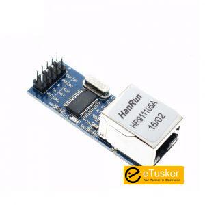
ENC28J60 Ethernet LAN Module
Description:
Chip board ENC28J60/SS
The board 25MHZ crystal
The network interface board HR911105A
3.3 V power supply pin
Size:5 x 2 x 1.5cm /1.92 x 0.72inch
Weight: 11g -
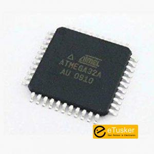
ATMEGA32A-AU
Specification:
- Clock speed: 16 MHz
- Flash memory: 32 KB
- 32 line output/input
- The JTAG interface
- Two 8-bit Counters
- One 16-bit counter
- Four channel PWM
- 8 channels 10-bit Converter analog-to-digital
- Hardware network interfaces: USART, SPI
- Six sleep modes
- Power Requirements: 2.7 V – 5.5 V
- Housing SMD
-
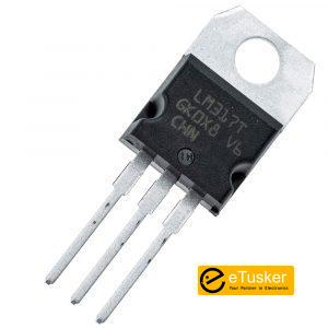
LM317T
The LM117 and LM317-N series of adjustable 3-pin positive voltage regulators are capable of supplying in excess of 1.5 A over a 1.25-V to 37-V output range and a wide temperature range. They are exceptionally easy to use and require only two external resistors to set the output voltage. Further, both line and load regulation are better than standard fixed regulators.
The LM117 and LM317-N offer full overload protection such as current limit, thermal overload protection and safe area protection. All overload protection circuitry remains fully functional even if the adjustment terminal is disconnected.
Typically, no capacitors are needed unless the device is situated more than 6 inches from the input filter capacitors, in which case an input bypass is needed. An optional output capacitor can be added to improve transient response. The adjustment terminal can be bypassed to achieve very high ripple rejection ratios that are difficult to achieve with standard 3-terminal regulators.
Because the regulator is and detects only the input-to-output differential voltage, supplies of several hundred volts can be regulated as long as the maximum input-to-output differential is not exceeded. That is, avoid short-circuiting the output.
By connecting a fixed resistor between the adjustment pin and output, the LM117 and LM317-N can be also used as a precision current regulator. Supplies with electronic shutdown can be achieved by clamping the adjustment terminal to ground, which programs the output to 1.25 V where most loads draw little current.
For applications requiring greater output current, see data sheets for LM150 series (3 A), SNVS772, and LM138 series (5 A), SNVS771. For the negative complement, see LM137 (SNVS778) series data sheet.
Shop By Department
- Hot Promotions
- Electric Vehicle
- Made in Sri Lanka
- Artificial Intelligence
- Buzzers, Speakers & Microphones
- Cables and Wires
- Enclosures
- Equipments
- General Accessories
- Boost Regulator
- Robotics
- Computers & Technologies
- Memory
- Modules and Sensors
-
Modules and Sensors
- Accelerometer
- Air Quality
- Ambient Light
- Angular and Linear Position
- Board Mount Pressure
- Current
- Flow
- Gyroscopes
- Hall Effect
- Image
- Load Cell
- Industrial Pressure
- Magnetoresistive
- PIR
- Proximity
- Sensor Development Boards and Kits
- Specialized
- Temperature and Humidity
- Fluid Level
- Vibration
- Angle
- Angular Velocity
- Attitude
- Color
- Current
- Gas
- Humidity, Moisture
- Infrared
- Magnetic
- Motion Sensors – Accelerometers
- Optical
- Position
- Pressure
- Temperature
- Touch Screen Controller ICs
- LDR
-
- Passives
-
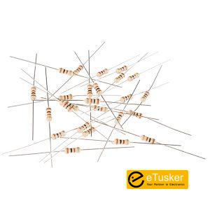
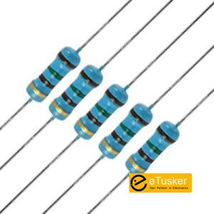
Resistors
- Carbon Film Resistors
- Cement Resistors
- Chassis Mount Resistors
- Chip Resistor – Surface Mount
- Fusible Chip Resistor
- High Power Surface Mount Resistors
- High Precision & Low TCR SMD Resistors
- High Voltage Resistor
- LED Strip Resistors
- Low Resistors & Current Sense Resistors – Surface Mount
- Low Resistors & Current Sense Resistors (TH)
- MELF Resistor
- Metal Film Resistor (TH)
- Metal Glaze Resistors
- Metal Oxide Film Resistors
- Metal Oxide Resistors
- NTC Thermistors
- PTC Thermistors
- Potentiometers & Variable Resistors
- Resistor Networks & Arrays
Capacitors- Aluminum Electrolytic Capacitors – Leaded
- Aluminum Electrolytic Capacitors – SMD
- CBB Capacitors
- CL21 Capacitor
- Capacitor Networks, Arrays
- Ceramic Disc Capacitors
- High Voltage Capacitors
- Metallized Polyester Film Capacitor
- Multilayer Ceramic Capacitors MLCC – Leaded
- Multilayer Ceramic Capacitors MLCC – SMD/SMT
- Mylar Capacitor
- Niobium Oxide Capacitors
- Super Capacitors
- Solid Polymer Electrolytic Capacitor
- Suppression Capacitors
- Tantalum Capacitors
- Trimmers, Variable Capacitors
-
- Connectors
-
Connectors
- Audio & Video Connectors
- Backplane Connector
- Banana and Tip Connectors
- IC Base
- IDC Box Header
- Barrier Terminal Blocks
- Card Edge Connectors
- Circular Connectors
- Connector – Card Sockets
- Connectors – Accessories
- Connectors – Housings
- D-Sub Connectors
- Ethernet Connectors/Modular Connectors (RJ45 RJ11)
- FFC, FPC Connectors
- IC Sockets
- Wire Terminal
- IDC Connectors
- LED Light Pipes
- SIM Holder / Connectors
- Lighting Connectors
- Lithium-Ion Model Connectors
- Mezzanine Connectors (Board to Board)
- Pin header / Male Header
- Pin Header / Female Header
- Pluggable System Terminal Block
- Power Connectors
- Rail Terminal Blocks
- RF Connectors/Coaxial Connectors
- Rectangular Connectors Housings
- Screw terminal
- Shunts & Jumpers
- Spring Clamp System Terminal Block
- Terminals
- Test Clips
- Test Points/Test Rings
- USB Connectors
- Wire To Board / Wire To Wire Connector
-
- Security and Protection
-
Security & Protection
- Security Cameras
- Alarm System
- Walkie Talkies
- CCTV Security Accessories
- Access Control
- Time Attendance Machine
- Video Doorbell
- Music Doorbell
- Security Gadgets
- Photography & Camera Acc
- Digital Cameras
- Sports Camera & Accessories
- Bags & Straps
- Camera Accessories
- Flashes & Accessories
- Lenses & Accessories
- Batteries & Chargers
- Plug & Adaptors
-
- Electromechanical
-
Switches
- Pushbutton Switches & Relays
- 5-way Tactile Switches
- Coded Switches
- Coded Rotary Switches
- Keypad
- DIP Switches
- Electrical Switches
- Industrial Control Switches
- Light Switches
- Limit Switches
- Metal Dome Pot
- Slide Switch
- Microswitches
- Multi-Directional Switches
- Pressure Contactor
- Rocker Switches
- Rotary Band Switches
- Special Switches
- Switch Accessories – Caps
- Tactile Switches
- Thermostat Switches
- Toggle Switches
-
- Development Boards, Kits, Programmers
- IOT
- Embedded Computers
- Semiconductors
-
Diodes
- Avalanche Diodes
- Bridge Rectifiers
- Constant Current Regulator
- Diacs Trigger Diode
- Diodes – ESD
- Diodes – General Purpose
- Diodes – Rectifiers – Fast Recovery
- Diodes – Rectifiers – Hyperfast
- Diodes – Variable Capacitance
- Gas Discharge Tubes – GDTs
- High Effic Rectifier
- High Voltage Diode
- Schottky Barrier Diodes (SBD)
- Switching Diode
- TVS Diodes
- Zener Diodes
-
- Integrated Circuits
-
Interface ICs
- 4-20MA
- CAN
- DDS
- Digital Isolators
- Ethernet ICs
- Interface – Signal Buffers, Repeaters, Splitters
- Interface – LIN Transceiver
- Interface-Specialized
- Interface-Telecommunications
- LVDS
- RS-485 & RS-422
- RS232
- Sensor Interface ICs
- Touch Screen Controllers
- USB
- Video-Audio Interface ICs
- Serial Interface
- Driver ICs
- Ballast Controller
- Darlington TransistorArray Driver
Power Management ICs- Battery Protection ICs
- DC-DC Converters
- Linear Voltage Regulators
- Low Dropout Regulators(LDO)
- PMIC – Battery Management
- PMIC – Power Distribution Switches
- PMIC – Supervisors
- Power Management Specialized – PMIC
- Power Module – Dedicated
- Power Modules
- Power Module AC-DC
- Switching Controllers
- Voltage References
-
- RF, Wireless
- Office Electronics
- Opto electronics
-
- Tools and Instruments
- RC
-
- CNC & 3D Printer
- Industrial
- Power
- Powers And Hand Tools
- Programmers
- Displays
- Prototype